1. Introduction
Roller inertia is one of most important topics (including bearing drag, air entrainment & roller pattern) when designs idler roller. In this article, it is analyzed how the inertia of roller impacting web tension, as well as explaining operational mathematics of the rollers, which helps engineers fully understand daily facing web issues (web-wrinkle & web-break) which are partially caused by idler rollers.
2. Analysis
Idler rollers don’t turn without applied torque, and this torque comes from forces at the roller’s surface. The torque to turn an idler will come from the web tension, either lowering it before the roller or raising tension after the roller, depending on whether the tension is controlled upstream or downstream from the roller, respectively.
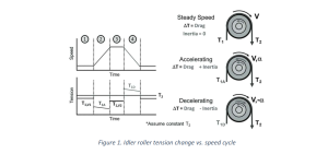
There are four stages to idler roller-induced tension changes, as shown in Figure 1:
1. Breakaway and low-speed bearing drag.
2. Combined torque of bearing plus inertia during acceleration
3. Bearing drag at high speed
4. Combined torque of bearing minus inertia during deceleration
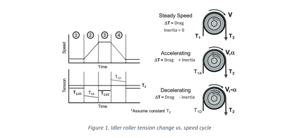

Change in force of idler roller (∆FT) can be described equivalently as web-tension at specific point in a series of idler roller. Bearing drag (restriction force of roller bearing) is one of noticeable section which discussed in section two.
Where moment of roller inertia is defined :

Rollers with different material are different Density (kg/m3), and showed detail in “Figure 2” for common material used to make idler rollers .
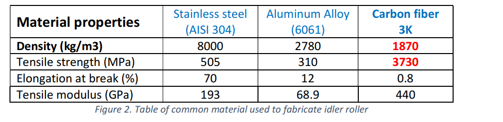
Basing on formular (1), (2) and figure 2, it shows “Carbon fiber 3K” roller has lowest inertia, equivalent to causing less stress on web (less tension losses).Tension losses from roller mass moment of inertia may be significant during speed changes, but can be minimized by either controlling acceleration and deceleration rates or avoiding aggressive manually applied speed changes. All processes need to accelerate from zero to process speeds and back to zero (unless the web breaks). Some processes inherently start and stop more frequently, including slitter-rewinders, zero-speed unwind splices or winder roll transfers, and step-andrepeat processes (e.g., traditional stamping or cut-to-length). More subtle speed changes are part of every moving roller or roll, such as the index cycle of turret winders and all dancer rollers.The tension changes from idler rollers are additive through a series of rollers, each contributing its own tension change. In a tension zone, the tension will rise moving downstream from bearing drag, increasing with speed (or bearing rpms). During
acceleration and deceleration, the MD tension change includes torque of inertia. If tension is closed-loop controlled by a load cell or dancer roller, the tension at that roller should remain at set point, but the tension several rollers upstream or downstream will change based on the number and performance of idler rollers.Figure 3 graphically shows the tension change through a series of rollers. During acceleration, the tension drops at the upstream end of the tension zone and rises at the downstream end. In extreme acceleration cases, the web could go slack on the upstream end. During deceleration, the tension rises at the upstream end of the tension zone and drops at the downstream end. In extreme deceleration cases, the web could go slack on the downstream end. Tension zones in draw control will have similar MD tension variations with constant tension at the downstream end of the zone, as if the closed-loop control roller is at the downstream drive point.These tension variations from steady speed to acceleration to deceleration can contribute to scratching, CD shifting, wrinkling, and other web handling problems, yet they will not be indicated by closed-loop control measurements.

Inertia is strongly a function of diameter, but diameter has a complicated effect on bearing drag. As roller diameter increases, the web’s leverage (through radius) increases, which reduces the tension differential compared to a smaller roller. However, as diameter increases, so does roller weight, slightly increasing drag. In addition, larger rollers tend to have larger bearings, which also increases drag. To this one must add inertial effects on tension during speed that increase with the cube of diameter, but the torque decreases only linearly. Thus, there is an optimum roller diameter for reducing tension differential. The optimum dimension may be slightly bigger than required by deflection if one is running very light weight webs that would need low tensions over a series of idlers .
3. Conclusion
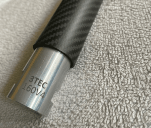
Together with advanced technology of material, carbon fiber is now the trend of market which used for idler roller especially in hygiene, paper industries with low basic weight and low MD tensile strength. The new material can be adequate to response aggressive speed change and avoid web break as well as significant web neck-down. Under pressure of using thinner and smaller slit width material to optimize product cost and machine waste, carbonroller is essential to improve machine performance and product quality especially running at high speed .
Copyright @ 2022 Published by 3TEC LTD. All rights reserved.